Prerequisites
⚠️ The installation of the module and its connections must be carried out by people with sufficient technical skills.
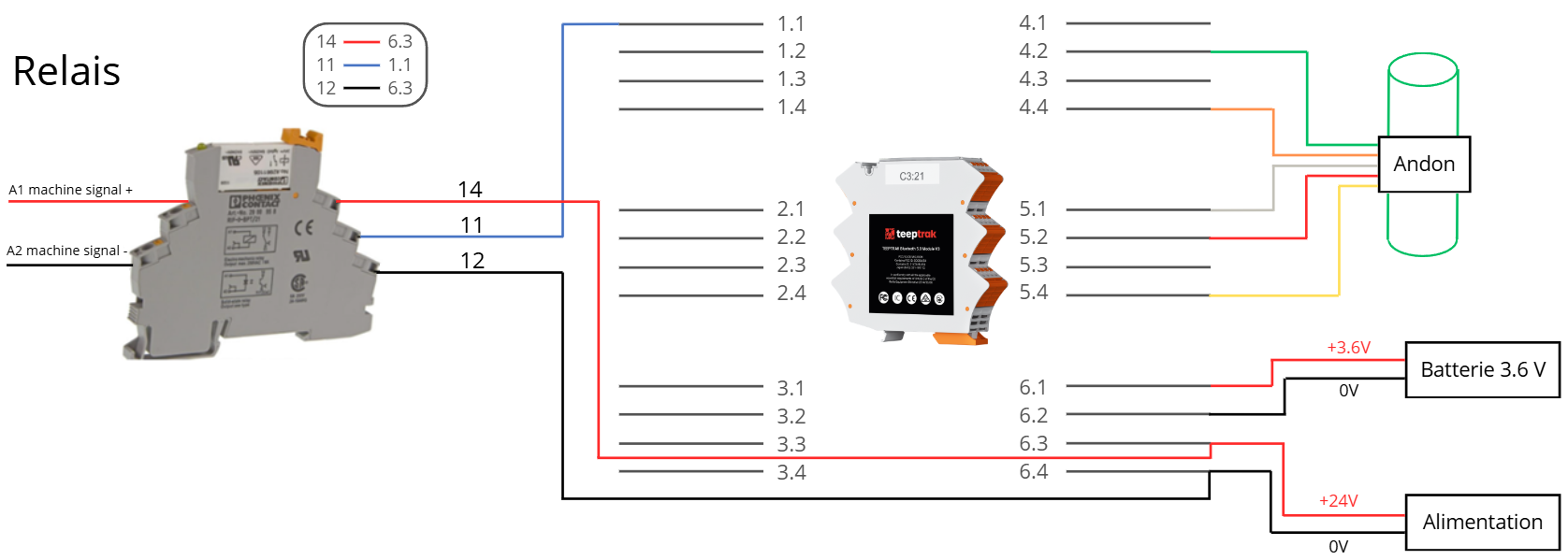
In the case of a direct connection to your equipment, we recommend installing an independent relay in order to eliminate any risk between the module and your equipment. No modification must be made to the printed circuit board: any modification or incorrect connection voids the warranty.
What you will need
When you receive your PerfTrak package, you will find:
1 TEEPTRAK DIN module
1 pre-assembled module box
1 light column
1 sensor (optional)
1 installation guide
Important information about the sensor
The signal is acquired by the TEEPTRAK electronic module. This module is compatible with most binary or analog sensors — the voltage must be compatible with a supply within the 5-25V range. The sensors can be contact, optical or Hall (magnetic) type, and can be replaced by sending a 0-24V voltage directly to the module, for example from a PLC output. It is up to you to define which type of sensor is best suited to capturing your machine's performance.
For the PerfTrak solution, a single sensor is required. On the Input connection, a voltage between 0 and +10.7V is considered low, and a voltage between 10.7V and 11.7V is considered high.
Important information about the power supply
The TEEPTRAK module box is connected to the main power and can be supplied with a voltage from 5 to 24V. This voltage is the one applied to the module outputs (OUT) as well as to the supply of the sensor connected to the module (IN).
⚠️ Caution: ideally, the power supply is continuous and separate from the monitored equipment, in order to avoid power cuts caused by machine stoppages. If the voltage exceeds 25V, a protection will cut the module's power supply.
Installing the module
Step 1: Fix the module on the DIN rail
Fix the PerfTrak module on the DIN rail of the pre-assembled box. All the connections are then made inside that box.
Step 2: Connect the components
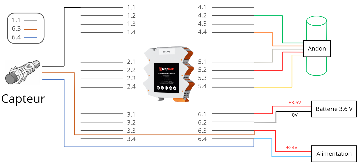
Using the installation guide provided in your package, connect:
The power supply: connect the red wire (+24V) from the main power to the module connector with reference 6.3. Connect the black or blue wire (0V) to the connector with reference 6.4.
The light column (Andon): connect it according to the diagram provided.
The sensor: connect it to the module's input connectors (IN), following the installation guide.
If you use a relay for a connection to an electrical machine signal, refer to the following diagram:
Step 3: Fix the box
Once the various connections have been made, fix the module box near the operator workstation using the mounting bracket kit provided, which is compatible with any flat surface.
Bluetooth connection distance between the tablet and the module:
Maximum range: up to 100 metres with no obstacle
Recommended distance: between 0 and 30 metres
If a sensor is used, fix the box next to the sensor.
Step 4: Check the power supply
Connect the power supply to the mains. If the red light on the module turns on, it is properly powered.
If in doubt
If you have the slightest doubt about the installation, contact the TEEPTRAK team to avoid any incorrect handling. The circuit is CE, IC and FCC certified.