The Defusing / Saturation feature is optional. Contact the Support team if you want it enabled on your installation.
Basic principle
If a machine depends directly on another one to operate, its performance may be distorted when that other machine stops. The Defusing / Saturation feature assigns downtimes to the right machine, by distinguishing those that are caused by a neighbouring machine.
Two phases are involved:
Saturation — the sensors associated with the upstream machine register a high signal beyond a certain threshold: parts accumulate because the downstream machine has stopped.
Defusing — the sensors associated with the downstream machine register a low signal beyond a certain threshold: no more parts are arriving because the upstream machine has stopped.
The system automatically detects and filters out these downtimes, which provides more accurate performance data.
Connection diagram
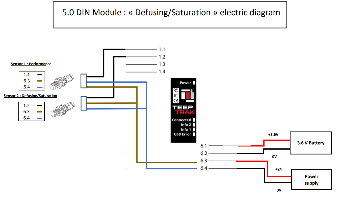
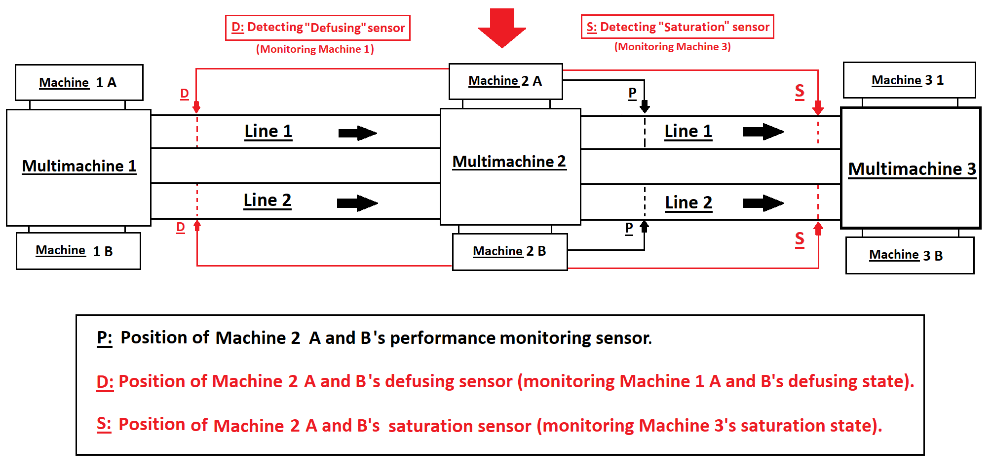
In a simple setup with two machines connected by a conveyor and located in two separate areas, the mechanism works as follows:
Machine 1 is in production and generates parts monitored by a sensor that tracks cycle times per product and machine speed (performance). A second sensor, detecting the saturation status, is also installed on the line and associated with machine 1.
The parts then travel along the conveyor to be processed by machine 2. Before processing, they are monitored by another sensor that detects the defusing status, associated with machine 2.
Saturation — machine 2 stops
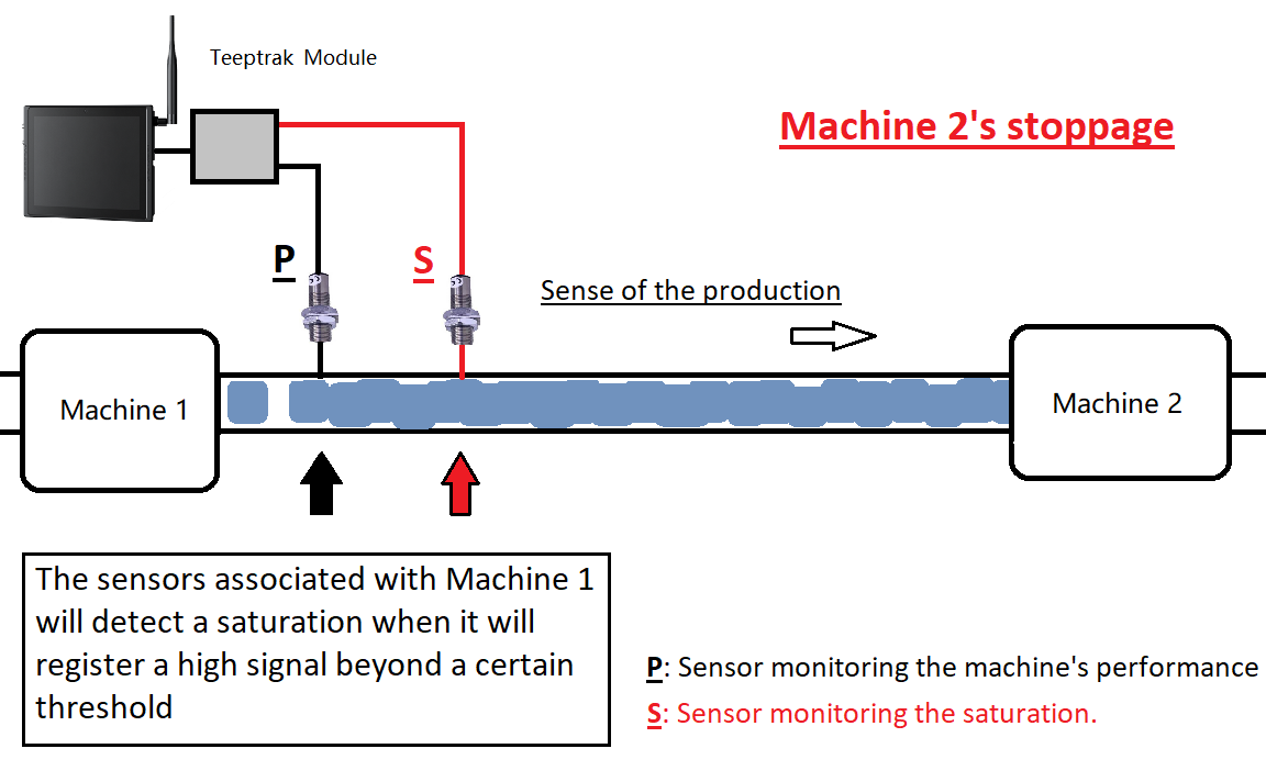
The sensors associated with machine 1 detect a saturation when they register a high signal beyond a certain threshold.
Defusing — machine 1 stops
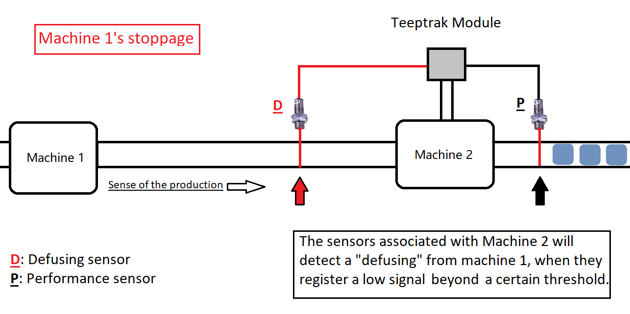
The sensors associated with machine 2 detect a defusing of machine 1 when they register a low signal beyond a certain threshold.
General explanatory diagrams
Mono machine mode
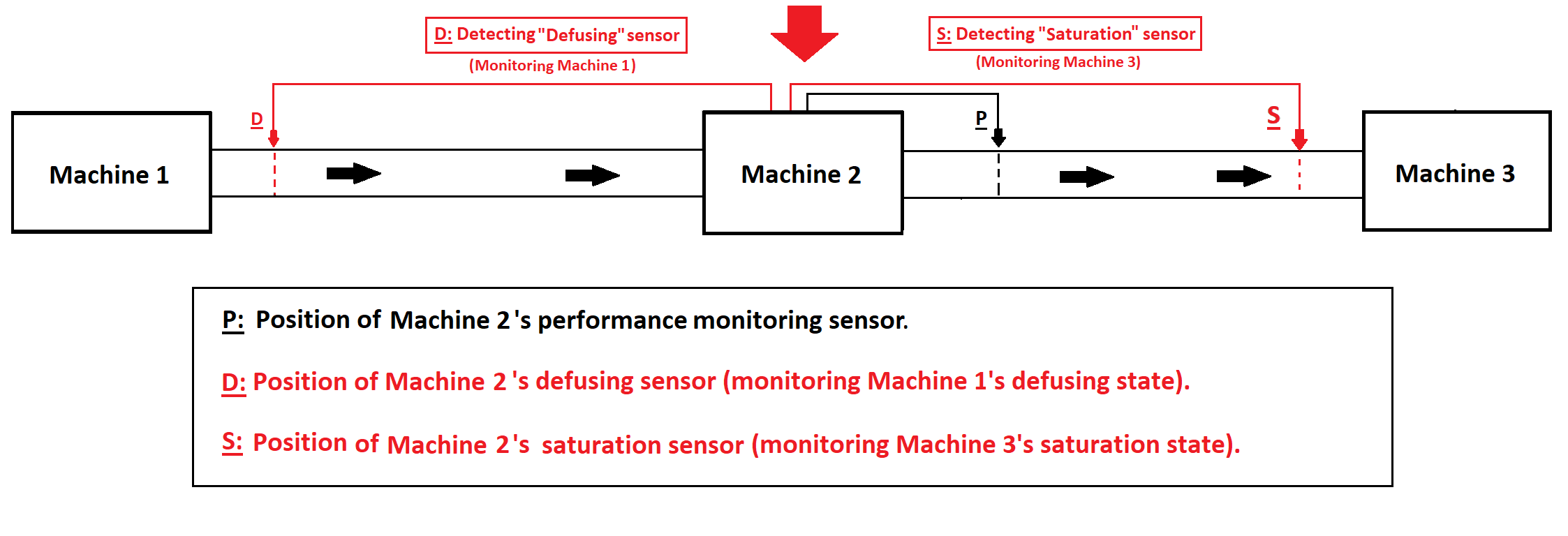
Multi machine mode
Web platform configuration
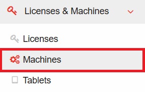
1. Go to the "Licenses & Machines" tab, then "Machines".
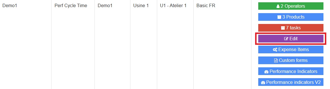
2. Select the machine you want to apply the feature to, by clicking its "Edit" sub-tab.
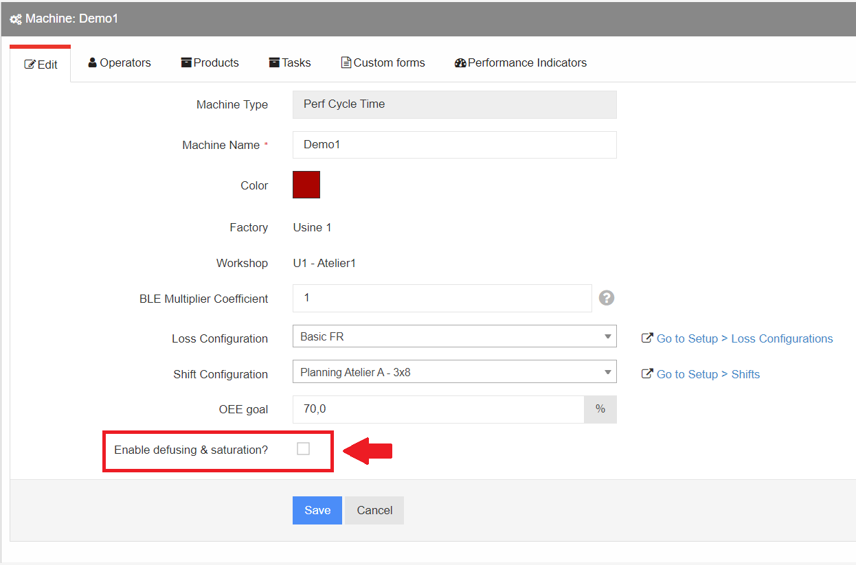
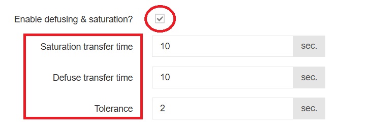
3. At the bottom of the machine's characteristics, tick the "Enable defusing & saturation?" box.
4. Then define the following values.
Saturation transfer time: threshold above which a saturation is triggered.
Defuse transfer time: threshold above which a defusing is triggered.
Tolerance (optional): delta between the theoretical qualifying time of a defusing / saturation and its actual triggering.
Trigger conditions
Defusing — the downtime must be greater than or equal to the cycle time, minus the transfer time, plus the tolerance.
Duration ≥ Cycle time − Transfer time + Tolerance
Saturation — the downtime must be greater than or equal to the cycle time, plus the transfer time, plus the tolerance.
Duration ≥ Cycle time + Transfer time + Tolerance
Tablet configuration
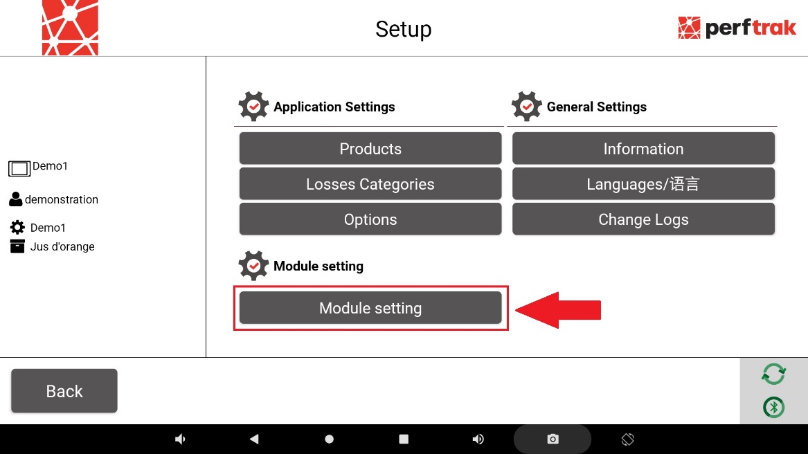
1. On the tablet, open the settings with the cogwheel at the bottom right of the screen, then select the "Module setting" tab.
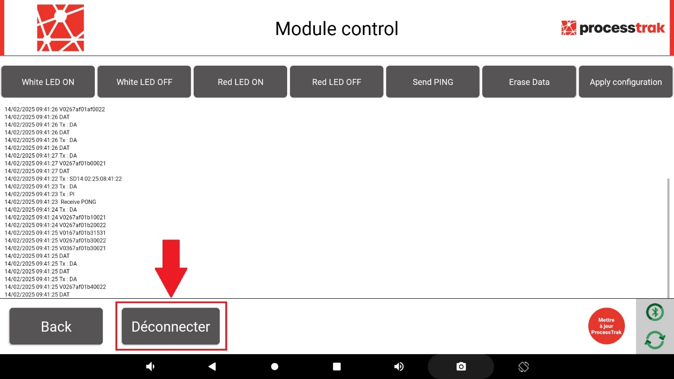
2. Click "Déconnecter" (Disconnect). This enables the modification of the sensor inputs through the tablet settings.
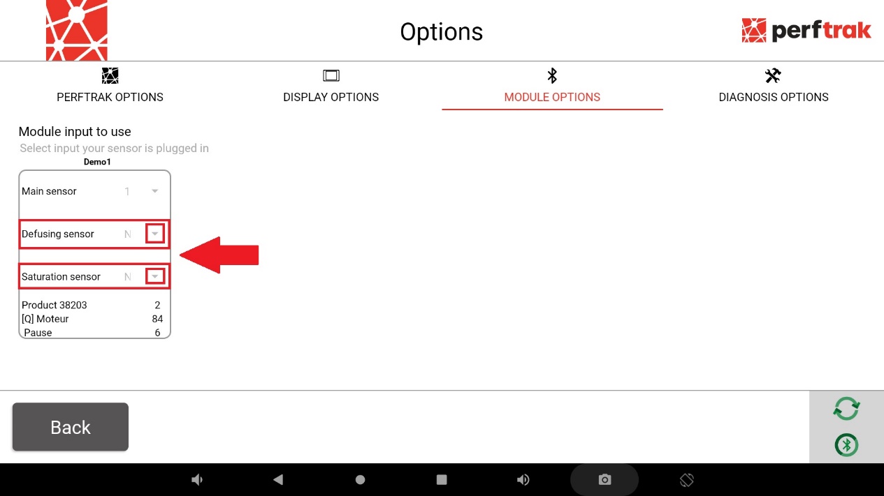
3. Go back to the application settings, click "Options", then "Module options", and choose the input each of your sensors is plugged into.
The main sensor, dedicated to performance monitoring.
The quality sensor, monitoring your production quality / scrap rate, if you use this feature.
The sensor(s) dedicated to saturation and defusing.
4. Once the module inputs are configured, reconnect to the module through the module settings. A red star indicates the last connected device.
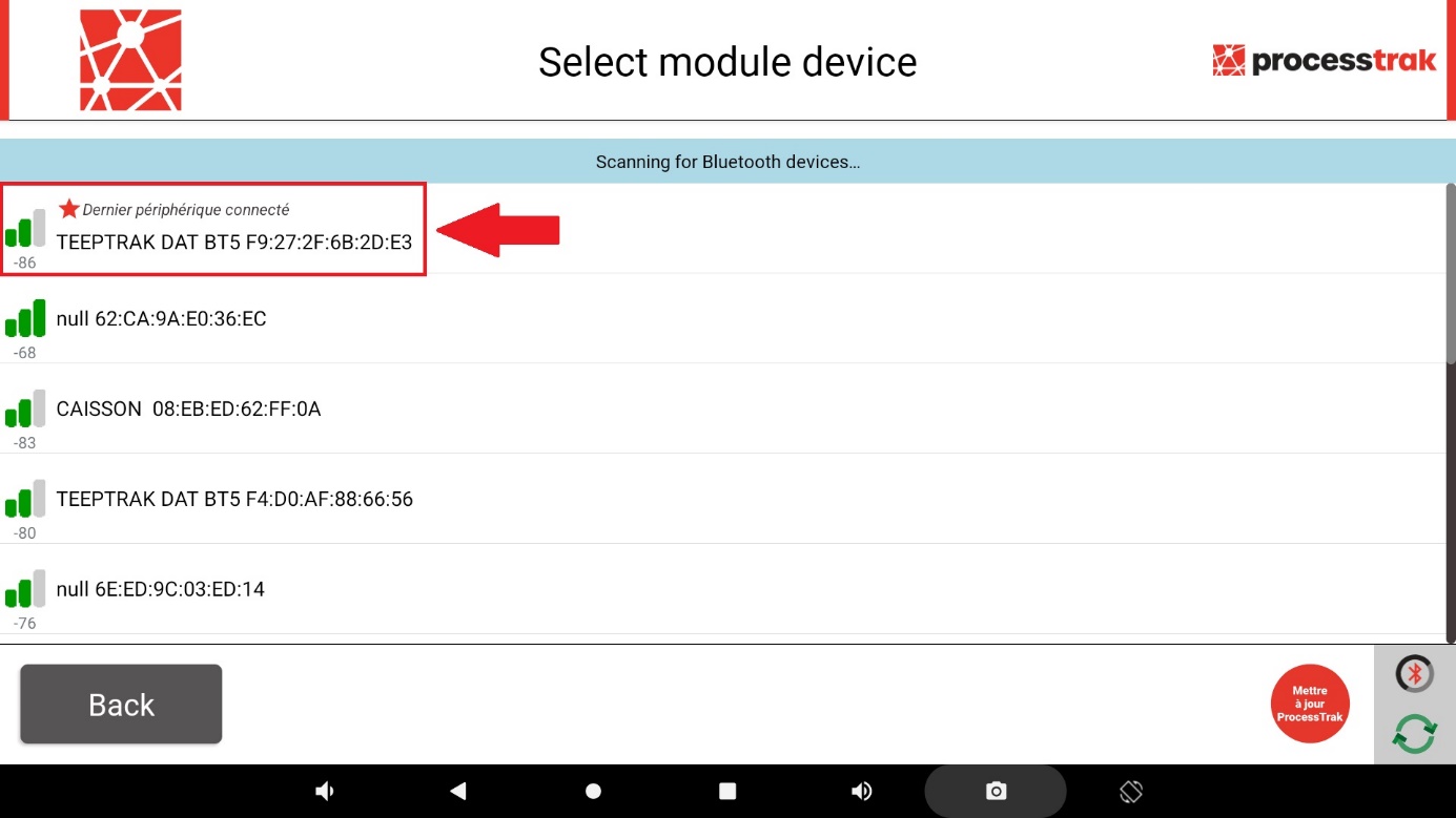
Once these steps are completed, the setup is finished.