Thanks to the Automatic Loss Management feature, you can automatically assign a loss type based on specific settings, by linking a signal to a defined cause. The signals associated with these losses are physically located at the module's inputs, with a distinct loss cause assigned to each input.
Module connection diagram
Single module mode, with relay
The module can be in standard mode or in input combination mode.
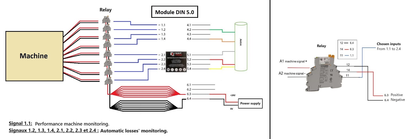
A module can receive up to 7 configurable inputs in addition to the main input, which is dedicated to performance monitoring. When using one module, the available inputs range from 1.1 to 2.4 — 8 inputs in total.
- If you use multi-machine mode, connect your machines (sensors and performance signals) to inputs 1.1 to 1.4.
- The remaining available inputs are used to receive the signals for automatic losses.
Multi-module mode
If you need more signals than the 8 inputs available on the main module, you can opt for multi-module mode: up to three modules can be added to the main one, for a total of 32 configurable inputs.
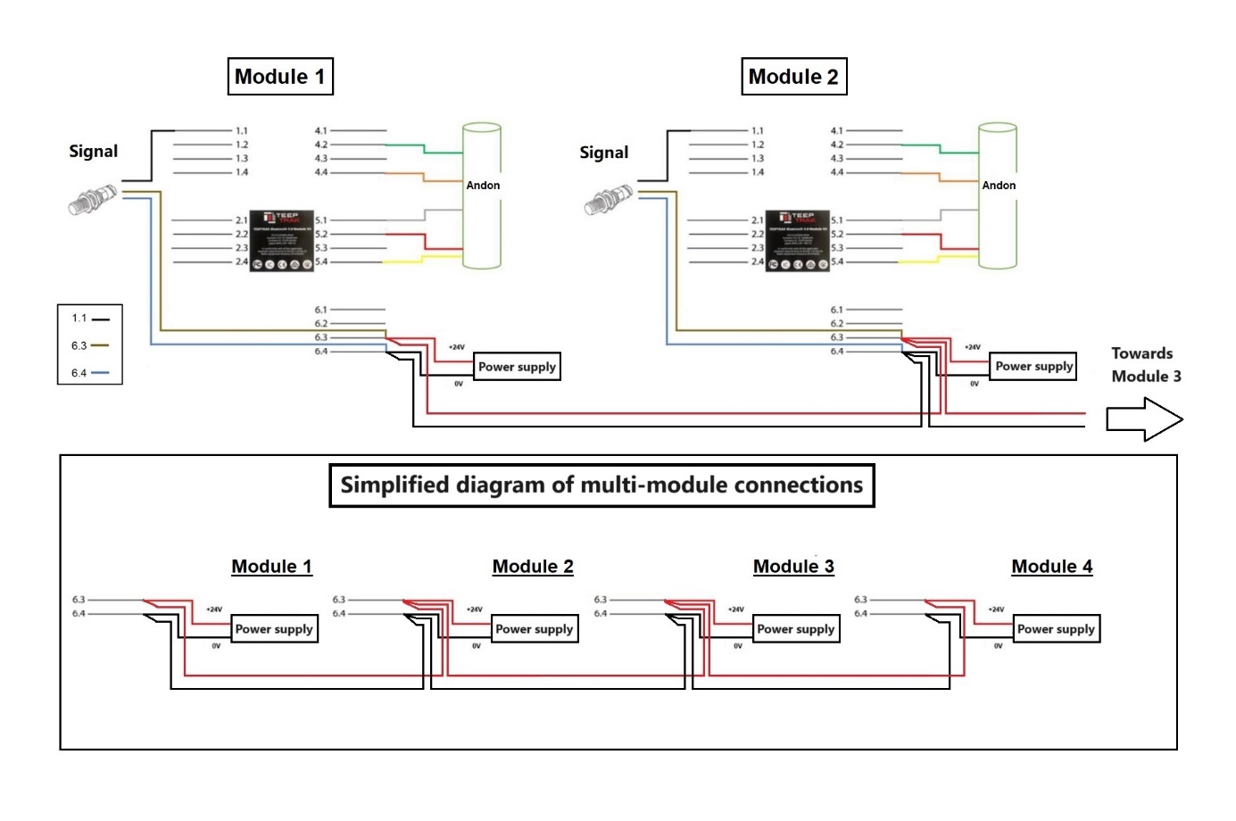
Each module offers up to 8 configurable inputs (1.1 to 2.4). Modules are connected to each other through inputs 6.3 and 6.4, doubled to the module to be attached.
- If you use multi-machine mode, connect your machines (sensors and performance signals) to inputs 1.1 to 1.4 of the main module, module 1.
- The remaining inputs available on the additional modules are allocated to receiving the signals for automatic losses.
Module inputs configuration
To select the type of losses associated with your module's inputs, you first need to define the level 1 and level 2 loss types you want to fill in automatically. As mentioned above, the signals for automatically informed losses must be connected to the module's inputs, each input corresponding to one loss type.
1. Log in to your configuration platform at www.teeptrak.net, then go to the Administration > Licenses & Machines > Tablets tab.
2. Select the tablet your machine and its module are associated with, click the "Modules" button on the right of the table, then click "Show inputs".
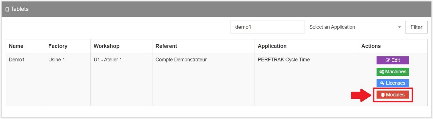
Inputs and their associated causes of loss
The list of the module's inputs appears, along with its associated loss tree — the "Loss Configuration" column. For each input, select its level 2 loss type.
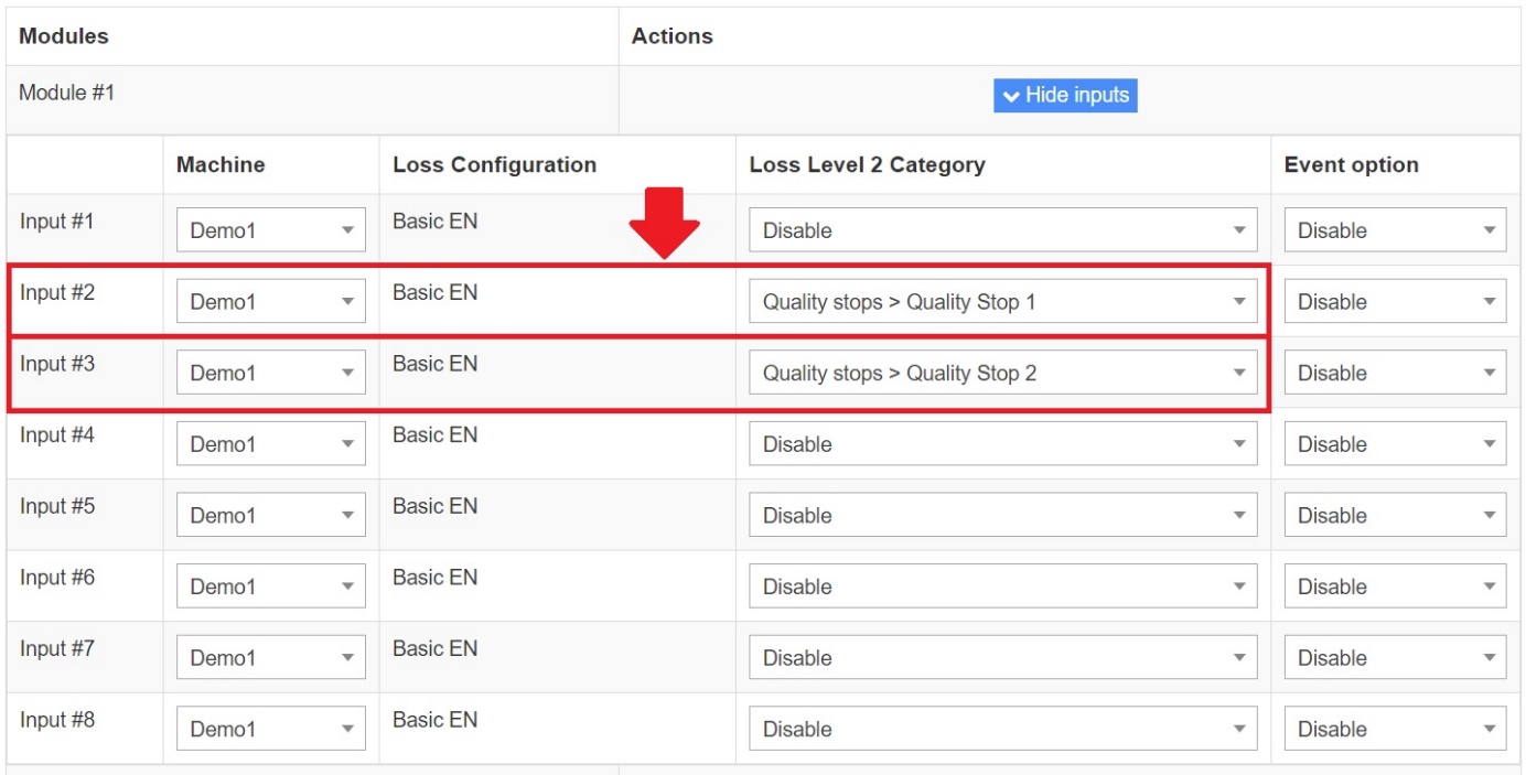
In the example above, a signal sent to input 2 corresponds to the level 1 loss "Quality Stops" and the level 2 loss "Quality Stop 1". A signal sent to input 3 corresponds to the level 1 loss "Quality Stops" and the level 2 loss "Quality Stop 2".
Note: input 1 is dedicated to monitoring machine performance and cannot be used for automatic loss management.
When using multi-machine mode, you must reserve as many inputs as there are machines linked to the module. For example, if you monitor 4 machines on inputs 1, 2, 3 and 4, you must start your configuration from input 5.
Selecting the signal capture option
The "Event option" column lets you choose how the signals generated by the module are interpreted and calculated, that is, how you want to scrap your production. You can scrap by product, or by pulse — which is useful when a grouping coefficient is used.
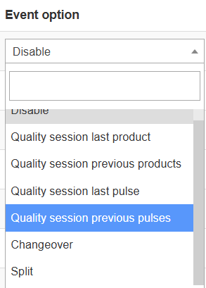
- Last product: scrap of the last product of the production cycle.
- Previous products: scrap by product.
- Last pulse: scrap of the last pulse of the production cycle.
- Previous pulses: scrap by pulse.
- Scrap before sensor: by pulse: automatic declaration of a scrap before sensor, of a whole pulse for each signal received. See the "Automatic scrap before sensor" section.
- Scrap before sensor: by product: automatic declaration of a scrap before sensor, of a single product for each signal received.
If you use a grouping coefficient, one pulse can correspond to several products. In that case, you choose to scrap the whole batch.
"Pulses" versus "products"
It is important to distinguish pulses from products. In a simple configuration, one pulse corresponds to one product. However, this does not always match the reality of production conditions: a grouping coefficient can be applied to your pulse, which then corresponds to a number of counted products.
Case study
With a grouping coefficient of 10, one pulse corresponds to 10 products. If you choose to scrap by product, it is not the whole pulse that is scrapped but the product — a tenth of the pulse. Only one product out of the 10 is scrapped.
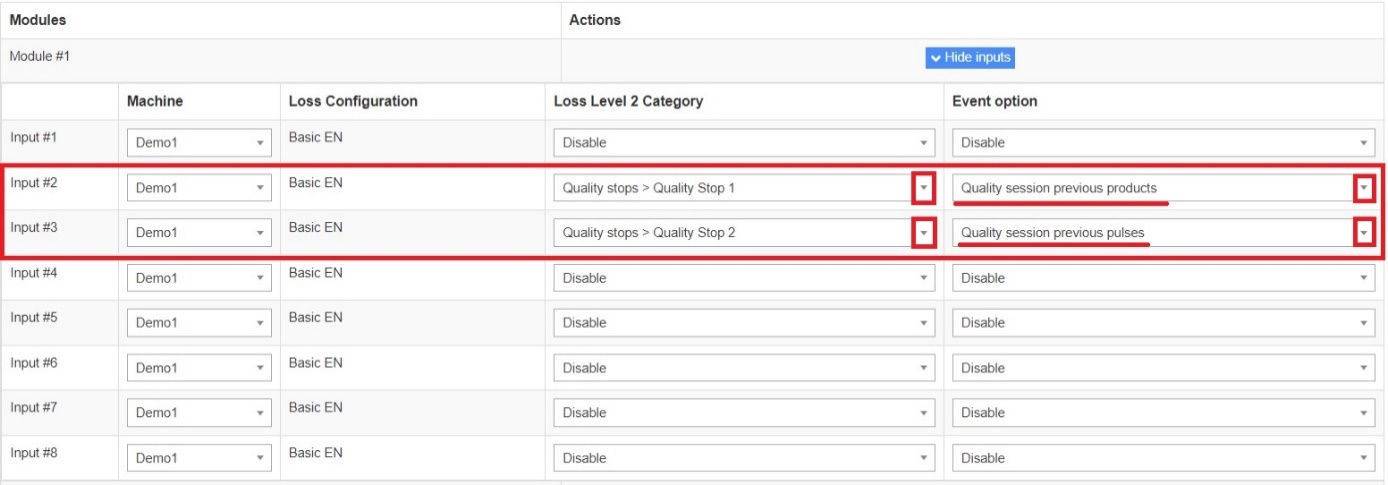
In the example above, the previous products put into production on input #2 are scrapped, under the automatic loss "Quality stops > Quality session previous products". The previous pulses on input #3 are scrapped under the automatic loss "Quality stops > Quality session previous pulses".
- The system automatically identifies and reports all the products or pulses, from the signals collected between two pulses of the performance sensor.
- The interval between two pulses of the performance sensor is what differentiates the counting ranges: scrapping on the last signal (last product or last pulse) versus scrapping on the previous signals (previous products or previous pulses).
Example with a grouping coefficient of 5, where 1 pulse equals 5 products:
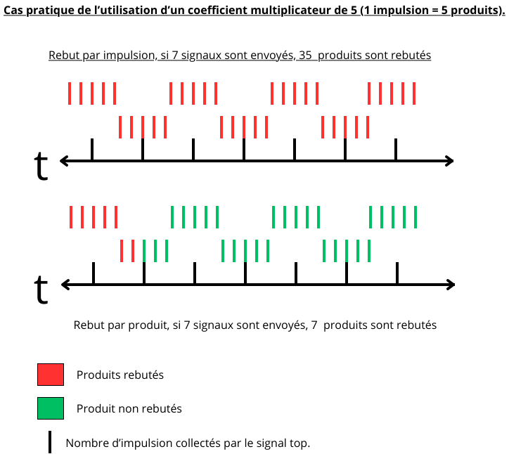
- Scrap by pulse: when 7 signals are sent, 35 products are scrapped.
- Scrap by product: when 7 signals are sent, 7 products are scrapped.
Other event options
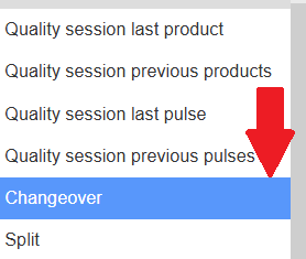
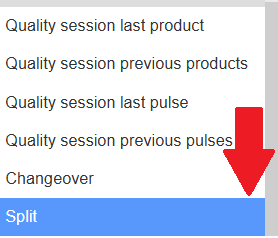
You can configure an input that indicates a change of product, by activating the "Changeover" event option. You are then asked to select the product concerned by this change.
The "Split" event option lets you configure a signal that divides the duration of a loss into two parts. The split occurs each time the associated signal is received, so a loss can be divided as many times as the sensor sends a signal.
Automatic scrap before sensor
On some lines, non-conforming parts are ejected upstream of the main sensor. These parts are never counted by PerfTrak. Declaring them as standard scraps would distort your count, because a standard scrap is deducted from the good parts.
With the Automatic scrap before sensor option, the ejection sensor is wired to a free input of the module. Each signal received on this input automatically creates a "before sensor" scrap:
- the scrap is added to the parts produced;
- it is not deducted from the good parts, since these parts never passed in front of the main sensor.
The operator has nothing to enter.
Prerequisites
- PerfTrak Cycle time tablet application v 1.1.322 or later. Earlier versions ignore this option.
- An ejection sensor wired to a free input of the module. Input 1.1 is reserved for performance monitoring. In multi-machine mode, the inputs of the monitored machines are not available either.
Configuration on the platform
- Go to the Administration > Licenses & Machines > Tablets tab. Click the "Modules" button of the tablet concerned, then "Show inputs".
- On the row of the input wired to the ejection sensor, select the level 2 loss category to assign to the scraps. This field is mandatory for this option.
- In the "Event option" column, choose one of the two scrap before sensor options.
- By pulse: each signal scraps a whole pulse. The scrapped quantity equals the grouping coefficient of the good parts. This is the right choice if the ejection sensor sees batches go by.
- By product: each signal scraps a single product, whatever the grouping coefficient. This is the right choice if the ejection sensor sees the parts go by one at a time.
Case study
The grouping coefficient of the product is 5. The ejection sensor sends 3 signals during the shift.
- By pulse: 3 × 5 = 15 products are scrapped.
- By product: 3 products are scrapped.
In both cases, the good parts remain unchanged. The parts produced increase by the number of products scrapped.
4. Save, then synchronize the tablet. Disconnect completely from the application, then log back in. Check that the input does appear in the module options, as described in the "Tablet setup" section.
Note: a change of configuration during a shift (cause, option) only applies to the signals received after the synchronization. The scraps already created are not modified.
What happens at each signal
For each signal received on the configured input, the tablet:
- creates a time-stamped scrap, with the default cause, attached to the current product and production order;
- calculates the production time corresponding to the scrapped parts, from the cycle time of the product;
- looks for this duration in the past slow cycle time to convert it into a quality loss.
The slow cycle search follows these rules:
- only slow cycle time is used, micro-stops are not taken into account;
- the slow cycle time must concern the same product or the same production order;
- it must still be present in the tablet history (see History duration on the tablet);
- it can be taken from several successive slow cycle periods;
- the rule is all or nothing: either the full duration is found and converted, or nothing is converted.
Important: scrap recorded with a quality loss of 0 s
If the tablet does not find enough slow cycle time, the scrap is created anyway. It is then associated with a quality loss lasting 0 seconds, and no slow cycle time is modified.
This case is silent: no message appears on the tablet or on the platform. It is frequent on lines that run above or at the nominal pace, since there is then no slow cycle time available.
Case study
The cycle time of the product is 12 s. A "by product" signal is received.
- The tablet finds 7 s then 6 s of slow cycle time on the same product, 13 s in total. 12 s are converted into a quality loss.
- The tablet only finds 5 s of slow cycle time. Nothing is converted: the scrap is recorded with a quality loss of 0 s.
Other behaviours to be aware of:
- Signal received during an ongoing loss: the scrap is created, but it does not qualify the ongoing loss. That loss still has to be informed by the operator or by another automatic input.
- Tablet offline: the scraps are created and kept on the tablet, then synchronized with the platform when the connection returns.
- No input configured with this option: the behaviour of the machine is unchanged.
Impact on the OEE
The scrap before sensor can have two effects, depending on whether slow cycle time was found or not.
Slow cycle time found: the duration is removed from the performance losses and assigned to the quality losses. The overall OEE does not change, but its breakdown is more accurate: the performance rate goes up and the quality rate goes down. The lost time is correctly attributed to non-quality, and not to a slowdown of the machine.
Scrap at 0 s: no time is moved: the OEE and its components remain unchanged. The scrap remains traced, with its quantity, its cause and its timestamp.
Note: the absence of an ejected part can create dead time on the line. This time is detected by the main sensor as slow cycle time, or as a loss if it exceeds the trigger threshold. In this second case, the loss must be informed like any other loss. Conversely, if the conveyor absorbs the absence of the part, no time is lost: the loss is material only.
Where to find the automatic scraps before sensor
The automatic scraps before sensor can be viewed on the platform, in the Loss history tab. Each scrap appears there with its cause, including those recorded with a quality loss of 0 s.
Difference from the manual scrap before sensor
| Manual scrap before sensor | Automatic scrap before sensor | |
|---|---|---|
| Trigger | Quality session started by the operator | Signal from the ejection sensor |
| Configuration | Tablet options | Module input, on the platform |
| Operator entry | Quantity, product, cause | None |
| Good parts | Not deducted | Not deducted |
To declare a scrap before sensor manually, see 7. Quality Sessions.
Input combination
By using input combination, you can configure one or more signals on each input, except input 1.1 which is specifically reserved for performance monitoring. This significantly enhances the module's ability to collect signals related to losses, scraps or triggers.
Input combination allows you to configure each of the module's 7 inputs (from 1.2 to 2.4) using a binary code, so a set of signals can be played — up to 7 signals can be assigned to each physical input. Signal collection through inputs provides up to 127 possible combinations in single-machine mode.
| Mode | Inputs reserved for performance | Inputs available for combinations | Possible combinations |
|---|---|---|---|
| Single machine | 1.1 | 1.2 to 2.4 | 127 |
| Multi-machine, 2 machines | 1.1 and 1.2 | 1.3 to 2.4 | 63 |
| Multi-machine, 3 machines | 1.1 to 1.3 | 1.4 to 2.4 | 31 |
| Multi-machine, 4 machines | 1.1 to 1.4 | 2.1 to 2.4 | 15 |
Configuring the loss inputs in combination mode
Once you have finished configuring the automatic losses by assigning a unique binary code, you then need to select, on the platform, the losses associated with the inputs that receive the combined signals.
1. On the platform, go to the "Licenses & Machines" tab, then "Tablets".
2. Click the "Module" button of your reference tablet. By default, several modules are displayed, up to 4, as long as input combination is not activated.
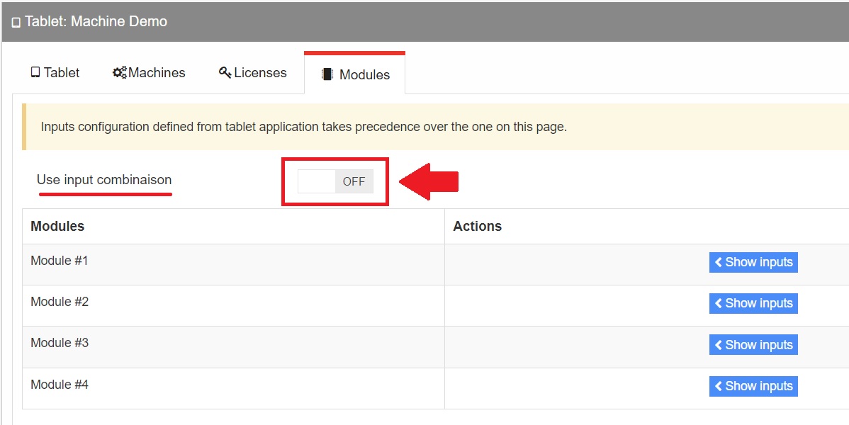
3. To enable input combination, click the greyed-out "Off" button next to the "Use Combinatory Mode" option.
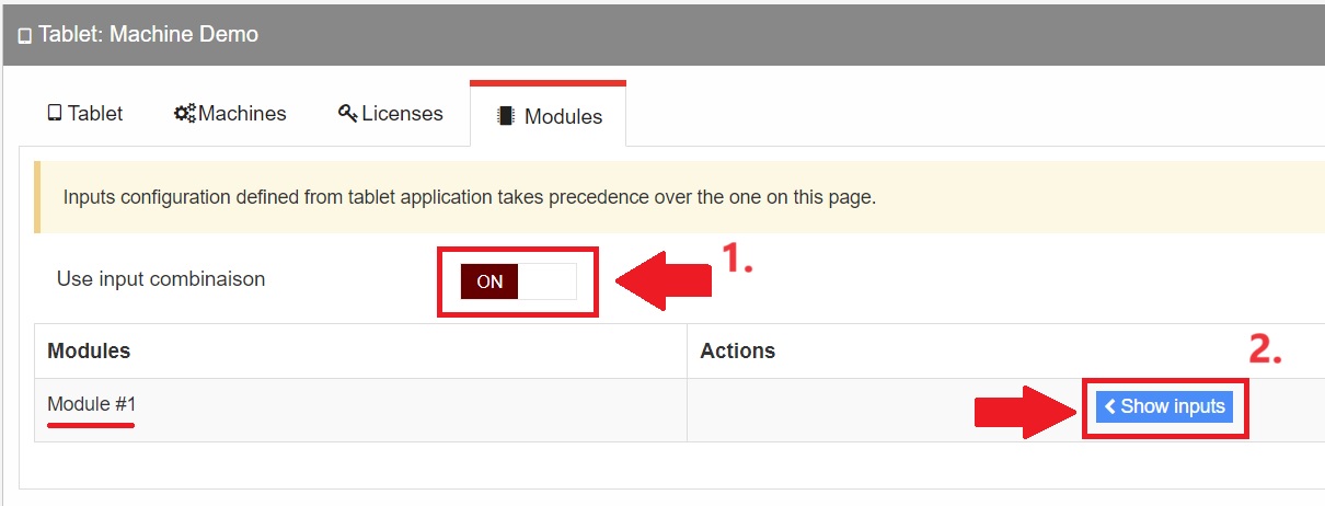
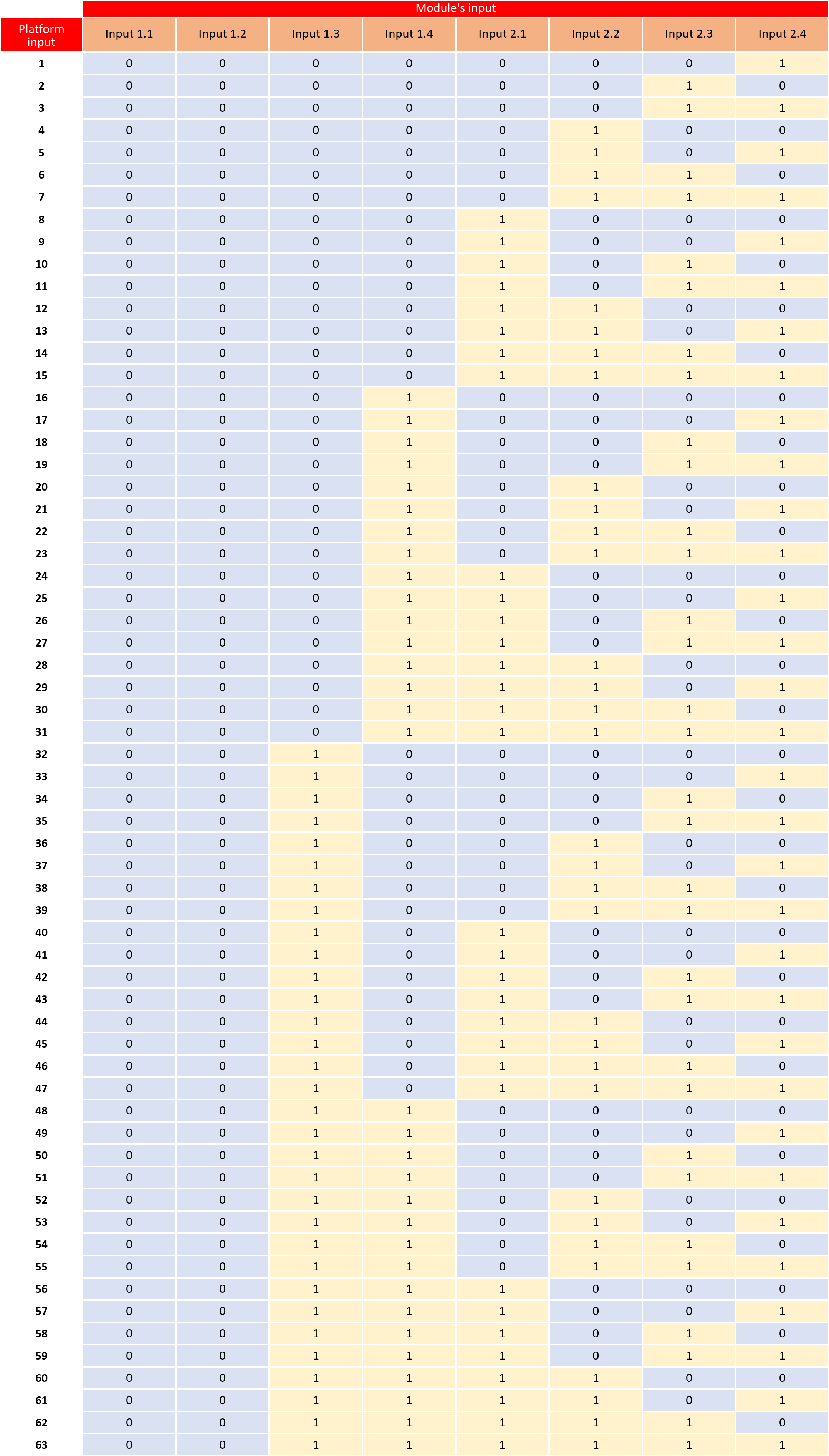
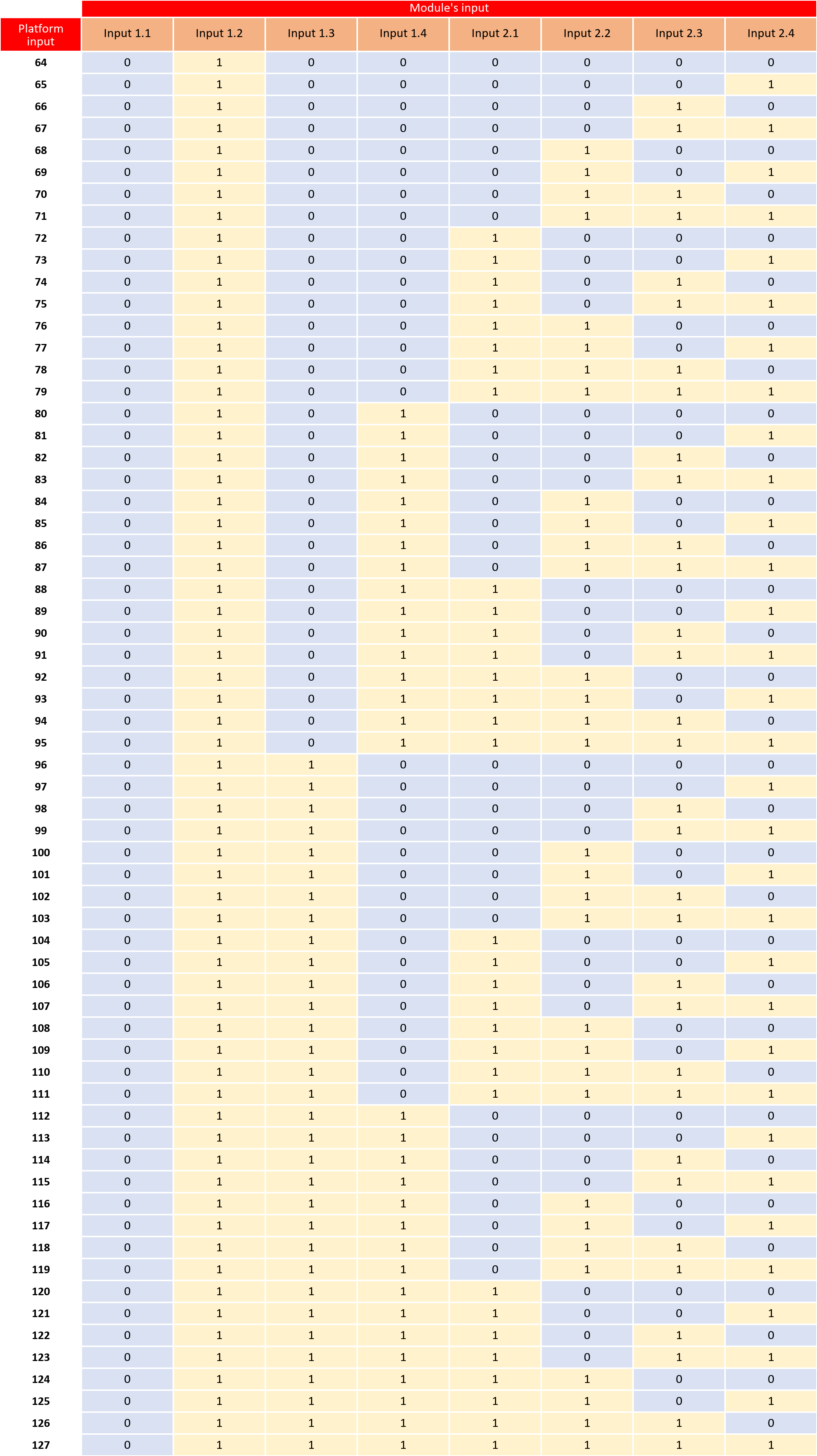
Reminder of the operating logic. There are 8 physical inputs on the module. Input combination allows you to combine several signals simultaneously on several of the module's inputs, to create a unique type of loss associated with a unique binary code. 127 combinations are possible using the module's 7 physical inputs, from 1.2 to 2.4. The 127 virtual inputs therefore correspond to the same number of signal combinations that can be configured on those 7 physical inputs.
Assigning the losses to the virtual inputs
The level 2 losses associated with the various virtual inputs carry the unique binary codes pre-configured from the loss tree. They are assigned from the module's input display interface.
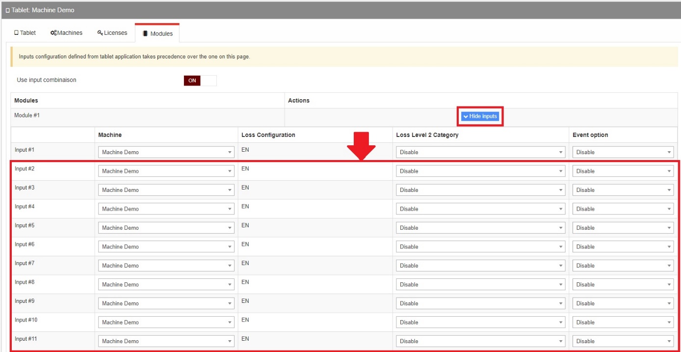
Level 2 losses are assigned in the "Level 2 Loss Category" column. As mentioned earlier, you can also add an event option — otherwise, leave it set to "Disable". Assign the level 2 losses of your choice to each of your virtual inputs.
Table of all possible combinations
In the table below:
- 0 is a low signal, or 0 volt.
- 1 is a high signal, or 24 volts, sent to the module input(s) of your choice.
Operating times and detected losses qualification
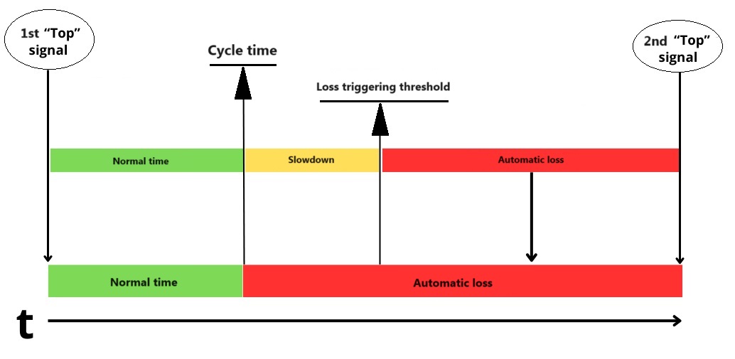
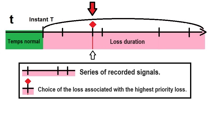
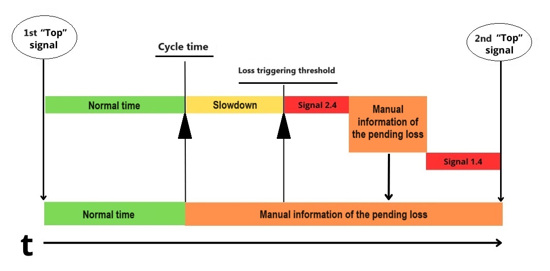
Principle 1. The duration of a loss is determined by two successive "top" signals, that is, the performance signal.
Principle 2. The durations of "normal operating times" and of "losses" are separated by the cycle time. The portion before the cycle time is classified as normal time, since it adheres to the expected duration for producing a part. The portion after the cycle time, which exceeds the predefined standard, is identified as a loss. If the loss duration does not exceed the second threshold — the trigger threshold for recorded losses — it is automatically classified as a slow cycle, and automatic losses do not apply.
Principle 3. Automatic losses qualify the entire detected duration of the ongoing loss. Automatic signals are not meant to split an ongoing loss.
Priority rules for signal processing
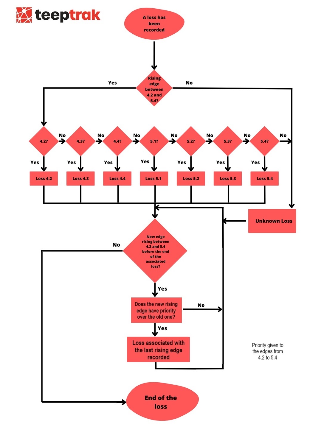
Priority to the signals closest to input 1.1
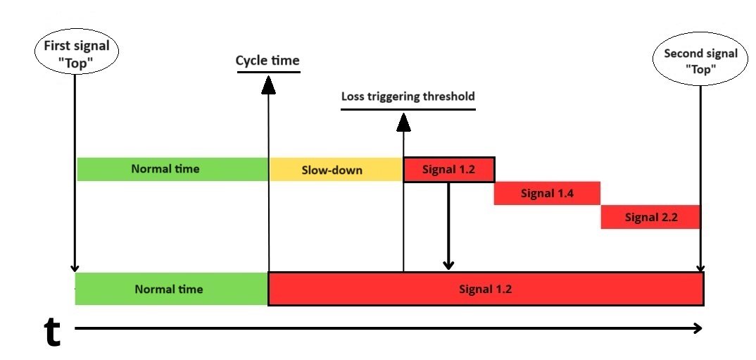
When using input combination, the signals associated with the combination closest to virtual input 1 have priority.
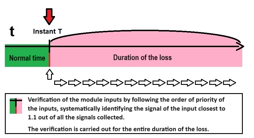
Example 1. If a signal is received on input 1.2, this input is the highest in the hierarchy. Any subsequent signal will not affect the loss classification: the loss remains assigned to signal 1.2 and its associated loss cause, regardless of the lower-priority signals received afterwards.
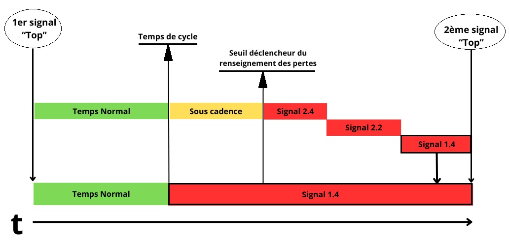
Example 2. When a signal is received on input 2.4, any signal closer to 1.1 is considered higher priority. If a signal is first received on 2.4 and then on 2.2, the 2.2 signal takes priority in determining the stop. If a third signal, 1.4, appears during the loss duration, it overrides the previous signals, as it is closer to 1.1.
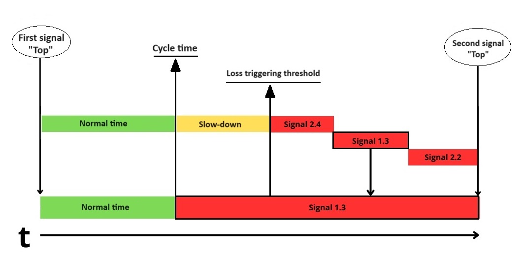
Example 3. If a signal 2.4 is received first, followed by a 1.3 signal, the 1.3 signal temporarily takes precedence in determining the stop. If a third signal, 2.2, is then received, it does not affect the stop classification because it has a lower priority than 1.3. Even though 1.3 is not the most recent signal, it remains the highest priority and ultimately defines the loss with its associated cause.
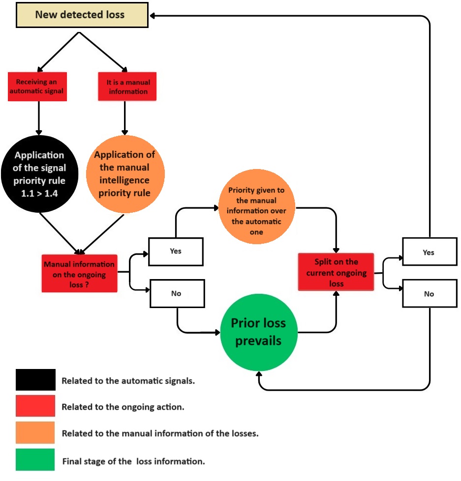
Priority to the operator
If the operator manually records an ongoing loss, the associated loss cause takes priority over the classification assigned by the system.
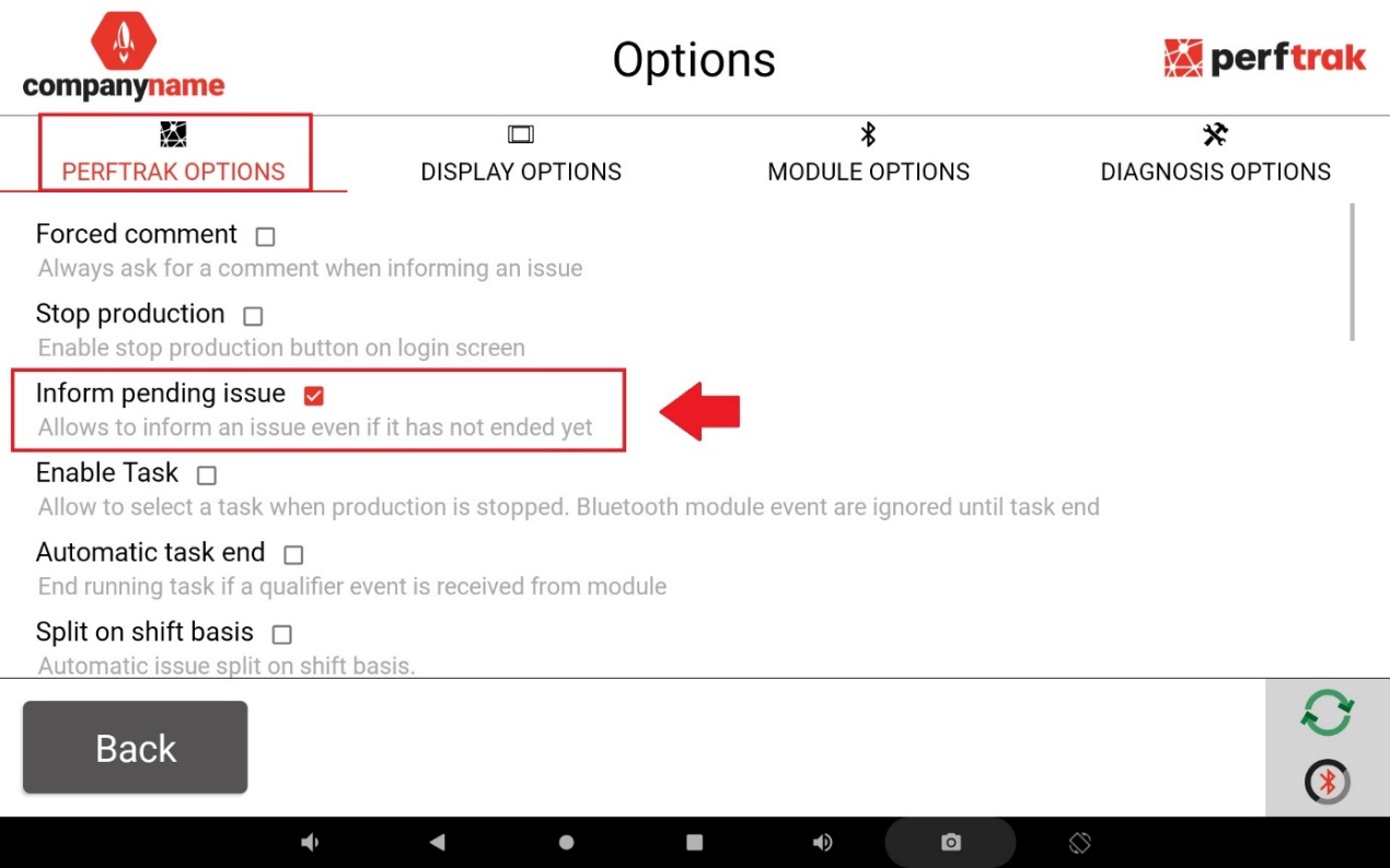
This option is optional and is configured in the PerfTrak settings on the tablet — see the section "Inform pending issue" option below.
Priorities with input combination
When using input combination, the signal combinations closest to virtual input 1 take priority over those on the other inputs.
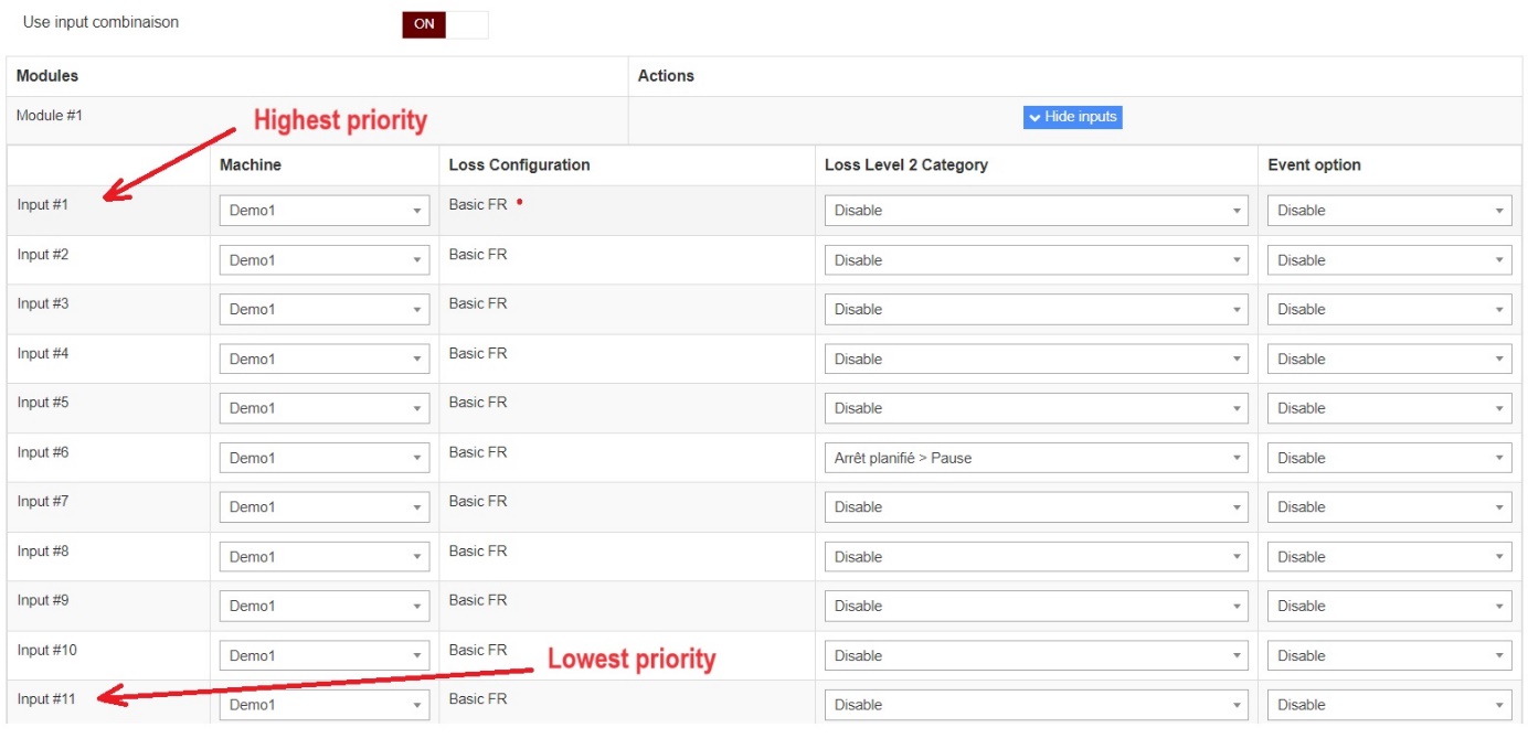
In the example above, virtual input #1 represents a combination of signals sent to the module under a single loss classification.
- Input #1: highest priority.
- Input #11: lowest priority.
"Inform pending issue" option
To allow an operator to record an ongoing loss, even before it has ended, this option must be enabled on the tablet.
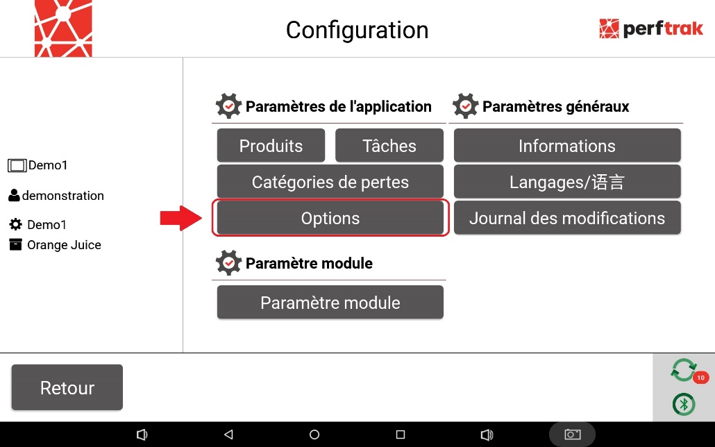
1. Open the settings by clicking the cogwheel icon, then select the "Options" tab.
2. In the "PerfTrak options" section, find and check the "Inform pending issue" box.
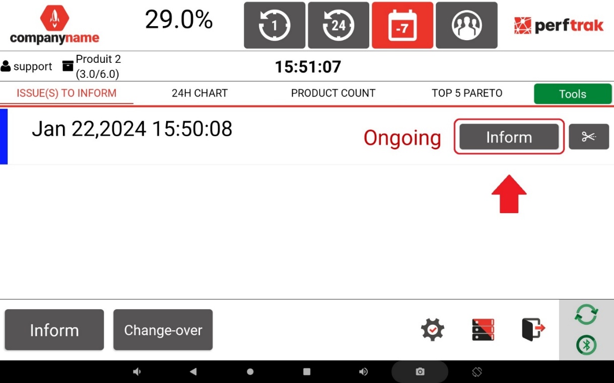
A box displaying the ongoing loss then appears on the tablet. The "Inform" button allows the operator to report the cause of the loss in real time.
Note: when an ongoing loss is recorded at a given moment, the entire loss duration — both past and future — is documented between two pulses of the "top" signal, that is, the signal tracking machine performance.
It is however possible to split an ongoing loss, to assign different loss causes to separate time segments within the same extended loss period.
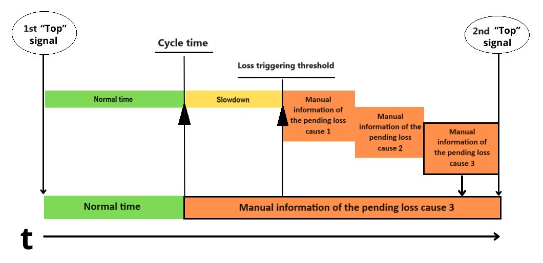
Multiple manual entries. When a loss is manually informed several times, the most recent entry takes precedence over the previous ones.
Split losses within a larger "main" loss. When manually informing losses several times and splitting stoppages, the split losses are independent of each other: each has its own start and end time, but remains part of a larger main loss, equal to the sum of all the split durations within it. The main loss is automatically detected between two "top" signals from the main sensor, and its duration is determined by the configured thresholds that distinguish normal time from loss time — the cycle time and the trigger threshold.
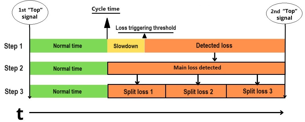
- Step 1: qualification of the time at each stage of its progression during the loss, in real time.
- Step 2: qualification of the time once the loss duration has exceeded the trigger threshold.
- Step 3: successive durations of the split losses, until the second signal is received.
A split loss can therefore occur:
- Between the machine's first "top" signal and the moment of the split — cause 1, in orange on the diagram.
- Between two splits on a pending loss — cause 2, in purple.
- Between the last split of the main loss and a new "top" signal marking the end of the stop — cause 3, in blue.
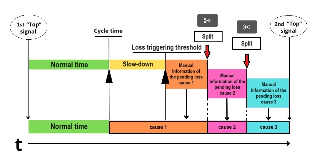
Application behaviour with automatic signals
Application behaviour with the "Inform pending issue" option
Prioritizing the first signal received
If you want only the first signal that qualifies the stoppage to take priority over all the others, do the following on the tablet.
1. Open the PerfTrak application settings with the cogwheel icon.
2. Select the "Options" button, then "PerfTrak Options".
3. Check the "First qualifier event priority" option.
Manual entry still takes priority over all received signals, including the signal from the first input.
Tablet setup
Once the configuration has been completed and saved on the platform, go to the tablet of your reference machine. To force the synchronization of the changes, first disconnect completely from the application by selecting the disconnect icon twice.
If you use input combination, the configuration is now complete. Otherwise, follow the procedure below.
1. Log back into the application and open the settings with the cogwheel icon. Click "Options", then go to the "Module options" section.
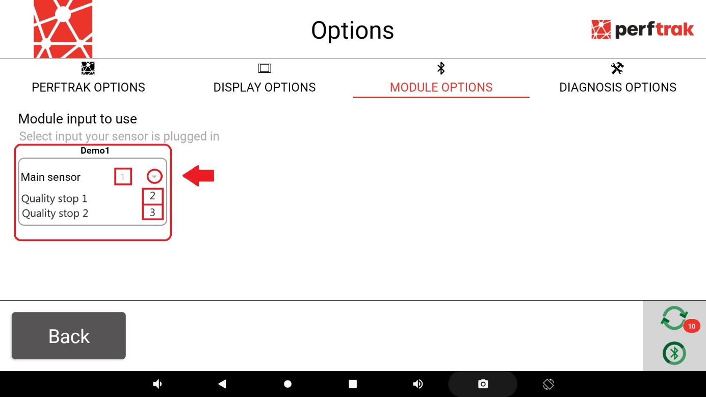
2. Check that every configured input is listed below input 1, which is reserved for performance monitoring. The inputs in use appear according to their number — 2, 3, 4 and so on, up to 8 usable inputs.
Thanks to these settings, you can associate a type of loss with a signal and automatically scrap part of your production.
If sensor detection does not appear, disconnect completely from the application and restart it. Disconnecting and reconnecting activates the synchronization of the data configured on the platform.
Important: you have to disconnect from the module in order to select the inputs of the automatic loss qualification sensor(s) from the module options.